

How Should You Connect a Turntable for High-Quality Vinyl Digitization?
Getting phono gain and RIAA equalisation in the right place matters more than choosing the most elaborate recorder. The route crosses two different analogue domains. The cartridge starts with a small signal that needs the correct loading, substantial low-noise gain and replay equalisation; only after the phono stage should the music be at line level and ready for an analogue-to-digital converter. A high sample rate and careful editing cannot rescue a signal that reached the converter at the wrong level or with the wrong tonal balance.
Our useful sketch is short: cartridge or turntable output, one phono stage, one line-level handoff and one ADC, followed by the recording file and its monitoring connection. Each job appears once. Connect a conventional cartridge output straight to an ordinary line input and the result will be far too quiet, without the normal replay curve. Feed one phono stage into a second phono input and gain and equalisation are applied twice. Those mistakes are obvious in the sketch, even when a row of familiar RCA sockets hides them on the equipment.
Multifunction products make the sketch more valuable, not less. A turntable may have a switchable phono stage, a phono stage may include USB conversion, and an amplifier may offer a record output that is already at line level. Name what each socket carries before connecting it: raw cartridge output, equalised line output or digital data. Then identify the component doing the conversion. A USB-equipped phono stage already performs several of these jobs; a conventional phono stage leaves the ADC choice open.
This guidance applies to post-1955 microgroove LPs, which generally use the RIAA replay curve. Earlier records may need a different curve and deserve specialist treatment instead of an automatic pass through a modern RIAA stage. For the usual LP collection, one condition settles the layout: the ADC must receive an equalised, usable line-level signal, with no concealed second phono circuit downstream.

Which Vinyl Digitization Topology Fits the Way You Want to Work?
The best vinyl digitization topology matches the archive you want to make and the controls you want to keep. All three sensible approaches still have to provide phono gain, replay equalisation, conversion, monitoring and file creation. Where those jobs happen determines which choices remain in your hands.
|
Route |
Choose it when |
Accept the trade-off |
Rule it out when |
|
Integrated USB phono stage |
Simplicity, a short path and one supported workflow matter most |
The phono stage and converter format are chosen together |
Cartridge fit, recording level, bit depth, sample rate or monitoring cannot meet the archive plan |
|
Phono stage into an ADC or audio interface |
You want to retain a chosen phono stage, use adjustable line inputs, capture at 24 bit or gain richer metering |
More boxes, settings and analogue connections enter the chain |
Stereo line operation, input mode, maximum level or connector fit is uncertain |
|
Phono stage into a standalone recorder |
Computer-free capture, portability or a lower-level safety recording is valuable |
A smaller control surface and later file transfer become part of the work |
The recorder lacks suitable stereo line inputs, lossless formats, input headroom or dependable monitoring |
An integrated USB phono stage suits an archive built around convenience. Rega’s Fono Mini A2D, for example, combines moving-magnet phono amplification, adjustable recording level and USB output in one component, with published 16-bit operation at 44.1 or 48 kHz. Its appeal is a shorter chain: fewer analogue handoffs, with the phono stage and converter fixed together. That same integration rules it out if you want to retain a favourite separate phono stage while choosing another converter or a 24-bit working format.
A separate interface makes more sense when the analogue playback system already has a phono stage worth preserving. The Scarlett 2i2 3rd Gen offers controllable line inputs, stereo direct monitoring and capture up to 24-bit/192 kHz. Its 6.35 mm TRS line inputs also show what this route asks of you. Select the actual line-input mode on both channels: mic and instrument modes are different operating conditions, however professional the socket looks. The two channels must also operate as a stereo pair.
A standalone recorder suits a different kind of session. The TASCAM DR-40X takes an external line input, writes files without a computer and can make a second recording at a lower level. That safety file helps with unpredictable material, provided you set the primary gain carefully; it cannot recover an analogue input that has already overloaded. Choose this route when independence from the computer genuinely helps. Follow the stereo line input, not the visual suggestion of built-in microphones or XLR-shaped sockets.
How Much ADC Headroom Should You Leave Before Recording?
Useful ADC headroom is room for the transient your test passage did not reveal. Digital full scale is a hard ceiling, and lowering the file later cannot restore a flattened peak. Vinyl makes a single average passage a risky guide: a louder cut, percussion strike or brief tracking event may still appear farther into the side. The meter does not need to look full. The capture needs to remain clean from lead-in to run-out.
With a 24-bit recording, conservative analogue gain is an easy bargain. Its working dynamic range lets you keep sensible peak margin without pushing the music towards 0 dBFS, although the cartridge, phono stage, wiring and converter still determine the real noise floor. Around -6 dBFS is a practical starting point, not a compulsory target. Play a genuinely loud passage, use peak hold instead of watching only the moving average, and leave more room when the record or cutting level is unfamiliar.
A dBFS meter shows level after conversion. It cannot show how much headroom remained inside the phono stage before the signal reached the ADC, because the analogue stage has its own ceiling. A modest recorded peak therefore does not prove that the incoming signal was undistorted. Match the phono stage’s possible output to the ADC’s maximum line-input level in the mode or range you have selected. The word “line” and a familiar connector do not help if the receiving input overloads first.
If a demanding passage sounds strained, make two short captures with genuinely different analogue ADC input-gain settings. If the distortion disappears when you reduce the hardware input gain, the ADC input path is the likely limit. If it remains while the recorded peak falls, look upstream to the phono stage and the earlier playback system. Move the real analogue control, not a software fader. A fader or later normalisation changes samples already written; neither can undo earlier clipping.
The converter also deserves attention as a component in its own right. Input range, noise, linearity, supported formats and monitoring facilities belong to the ADC, even when it shares a case with a phono stage or recorder. A 24-bit/192 kHz headline may be attractive, but the chosen input mode must accept the phono stage’s stereo output cleanly—without overload, awkward adapters or an unintended mic circuit. Sample rate and cable choice cannot create electrical headroom.
Should You Monitor Through Hardware or Recording Software?
Your recording monitoring path should tell you which point in the system you are hearing. Direct monitoring sends the converter input to headphones or outputs without waiting for the computer. That makes it immediate and useful for detecting hum, distortion, channel imbalance and the signal arriving at the interface. Software monitoring returns the input through the recording application, so it includes the computer’s routing choices but may add latency.
Either method can work well. The trouble begins when both are active by accident: the doubled or slightly delayed sound can resemble a cartridge, alignment or phase problem. Choose one monitoring method for the session, keep left and right placement obvious, and listen loudly enough to catch buzz and breakup without turning the check into a performance.
Hearing the input is not the same as proving the recording. Direct monitoring may sound entirely correct while the application writes the wrong input, records in mono, uses an unwanted format or fails to complete the file. Software monitoring reaches farther through the system, but the reopened file remains the final witness.
What Makes a Vinyl Test Capture Trustworthy?
A trustworthy vinyl test capture brings ears, meters and waveform together. Listening can reveal hum, buzz, mistracking, distortion, swapped channels and an obviously doubled monitor feed. Peak metering shows how close the converter came to full scale. The waveform may expose a discontinuity, a missing channel or a suspiciously flat-topped peak that passed too quickly to diagnose by ear. Each view catches something the other two can miss.
Start with a representative loud passage, then include a quiet lead-in or run-out where low-level noise and channel behaviour are easier to hear. Save the short recording in the intended lossless format. Stop the application and reopen the file as though someone else had sent it to you. That small break is more persuasive than an unsaved waveform still sitting in an active project. Check its duration, stereo orientation, sample format and playback before committing a complete side.
Keep the preflight short enough to become a habit: find the error while the record can still be replayed. Thin peak margin calls for lower analogue input gain. Trace a missing channel before continuing. If the reopened file differs from the monitored input, examine the software or export process. Once those checks are clean, begin the full-side transfer with the same headroom—and remember that the next track may still contain a hotter transient.

Which File Should Remain the Untouched Vinyl Archive Master?
The vinyl archive master should be the lossless, unedited result of the successful capture. Preserve it before click removal, normalisation, track splitting or any other change. WAV is a straightforward choice. BWF adds a structure for archival metadata when that is useful, and AIFF can provide an immediate lossless safety export in suitable software. The important boundary lies between the untouched source file and every later interpretation of it.
Make listening copies from that master. You may remove clicks from one, normalise another for a library, and create compressed files for a phone or network player. The untouched file preserves your freedom to make another restoration or delivery choice later, without putting the stylus on the record again. Never let a processed or lossy copy become the sole survivor of a careful transfer.
An immediate safety export is worthwhile, but preservation goes further. Give the master a stable name, retain the capture settings and keep another copy on separate media or in a separate location according to the recording’s importance. Audition the reopened master instead of trusting the editing project. The archive becomes real when that independent file can be found, opened and played, still unaltered from the captured side.
When Can RHOD Belong Between the Phono Stage and ADC?
A line-level interconnect belongs after phono gain and RIAA equalisation and before a separate ADC receives the phono stage’s line output. Once you have chosen those two components, the final analogue span remains part of the system. The music is already amplified and equalised, but connector execution, screening, construction, length and physical placement are still open choices before conversion turns it into data.
We offer the RHOD Reference analog interconnect for that position in RCA-to-RCA and XLR-to-XLR configurations. Connect it from the line output of a phono stage to the matching line input of a separate ADC. A mic input, instrument input or TRS-only interface is a different endpoint, even if an adapter exists. The cartridge-to-phono connection is different as well, because that low-level circuit has its own loading and connection requirements.
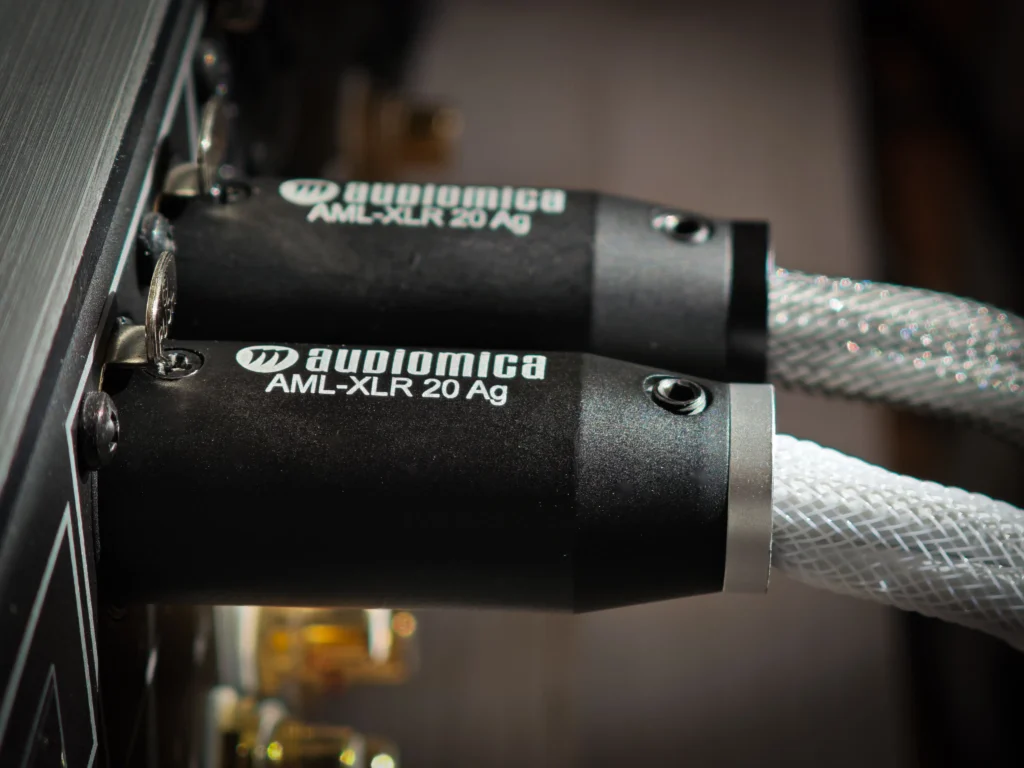
For this line-level span, RHOD uses OFC 6N conductors with a copper-braid screen. Its two 0.81 mm conductors each have a 0.51 mm² cross-section, and the cable is approximately 8.5 mm in diameter. We hand-terminate the current version. The RCA configuration uses our AML-ACP-RCA01 Au split-pin and screw-casing construction; the XLR configuration uses an AML-XLR10 Au solid-metal, non-magnetic body.
Both connector versions have 24-carat gold-coated, DCP-treated surfaces, a treatment we apply in pursuit of conductivity and durability. Our guide to connector construction and stable contact looks more closely at contact geometry, body materials, surface treatment and termination. For a listening comparison, leave the levels and capture system unchanged. Then listen in your own system for the clarity, pace, dimensionality and bass control that we associate with RHOD.
RHOD comes in six configurations, with standard lengths from 1 to 5 metres, a custom-length field, available antistatic couplers, and optional DFSS Premium or TFSS Luxury filters. Choose the shortest comfortable length for the installation, then the connector and filter configuration that suit it. The phono stage still handles replay and the ADC still makes the digital master. RHOD concentrates on screening, connector construction, hand termination and configuration in the analogue connection between them.


