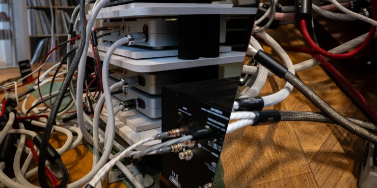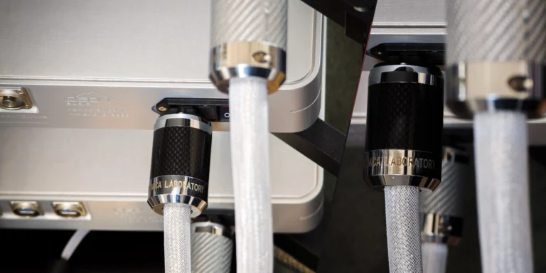

Can You Move an External Hi-Fi Power Supply Farther Away With a Longer DC Cable?
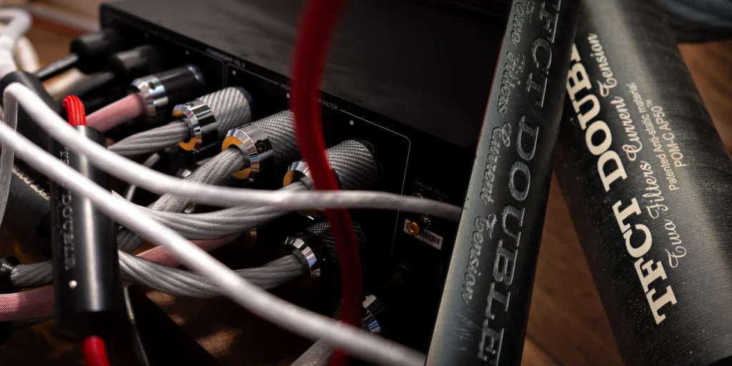
A longer DC power cable can free shelf space or make a rear-panel connection easier to reach. We consider that a worthwhile refinement when the whole connection remains suitable for the equipment it powers. That means looking beyond the plug to the component's input requirements, the voltage reaching it under load, the connectors and the way the cable sits in the rack. The aim is to find a better place for the supply and accommodate the connection properly between the two boxes.
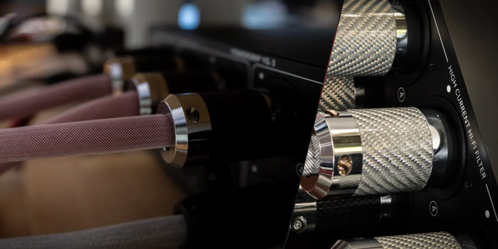
What Should Moving the Power Supply Achieve?
Start thinking about power supply placement with something you want to improve in the rack. Perhaps the supply occupies shelf space you could use elsewhere, its socket is difficult to reach, or it sits awkwardly behind the equipment with little support. Name that improvement before choosing a cable length. Moving the supply farther away gives you more cable to accommodate; it need not give you a better installation.
Imagine a supply sharing a crowded shelf with a small source. A suitable adjacent position could leave more room for the source's connections and make both units easier to reach. The useful distance ends at that better position, with enough cable to follow its actual course between them. Once access and support are satisfactory, moving the supply farther away adds nothing to the original purpose.
We would first try a different shelf assignment or a modest change of position with the supplied lead. Keep the original lead if it comfortably serves the improved layout. There is good reason to retain a known assembly when extra length would introduce an awkward joint or a stiff bend. A longer lead becomes interesting when a worthwhile position lies beyond the supplied cable's comfortable reach.
There is real value in a rack that is easier to use and a connection that sits properly. Extra separation alone establishes neither lower noise nor better sound; those outcomes depend on the particular system. Take the installation seriously for the improvement you can identify, without assigning a sonic reward to each additional metre.
Which DC Requirements Must Stay the Same?
The component's DC input requirements tell you what must arrive at its receiving socket. Consult the instructions for the exact model and its specified supply, and keep that supply while considering the move. The voltage printed on the power brick is useful, but it cannot tell you everything the component will accept through a longer connection.
Distinguish the nominal voltage from the allowed input range. The RME ADI-2 DAC FS user guide, for example, specifies a nominal 12 V supply and an input range of 9.5–15 V. That tolerance applies to the RME device. Another DAC, streamer or phono stage marked 12 V needs its own requirements checked. Figures for a similar-looking product cannot fill a gap in its instructions.
Assess the longer assembly against the documented operating demand, including relevant peak demand where specified. An idle component shows you only one operating condition, so a connection chosen around that observation may fall short of the full requirement. Use the stated demand rather than inventing a startup surge or current profile, or assuming that idle demand is all the component will need.
A cable described simply as suitable for “12 V equipment” still needs to answer a more specific question: can it serve this component, with this supply, throughout the required operating conditions? Look for a documented match between all three. If you cannot establish it, keep the supplied lead and change the shelf arrangement. That can solve the placement problem just as completely, even if the supply ends up somewhere other than your first choice.
Why Is a Matching-Looking Plug Not Enough?
Reliable DC connector fit depends on dimensions, polarity, ratings and retention. For a barrel connector, the inner and outer diameters are separate measurements; its usable barrel length must also suit the socket's insertion depth. The common 5.5 × 2.1 mm and 5.5 × 2.5 mm combinations differ despite sharing an outer diameter. That shared measurement does not make them interchangeable.
A replacement plug must engage as intended and stay in place without pressure from the cable holding it there. Merely entering the socket is insufficient. An exact connector specification is worth more than a familiar-looking photograph. Identify it from an assembly drawing or an equipment-specific designation rather than trying a selection of nearly matching plugs on powered equipment.
Check the specified polarity and electrical ratings through the entire connection, including any extension. Centre-positive is common among barrel connectors, but centre-negative connections also exist, and neither voltage nor current rating can be read from size or appearance. Proprietary multi-pin wiring and multiple supply rails call for the manufacturer's exact supported assembly. A plug can feel mechanically convincing while leaving these electrical questions unanswered.
We would also preserve the way the original connection is secured. Standard barrel connections may lack a positive lock; threaded and twist-lock versions can secure the mating parts. The RME manual describes a 90-degree locking turn after insertion for its supplied connection, an action specific to that model. Gaining length at the expense of a useful lock is a compromise, especially behind a rack that moves for access. Retain the lock alongside the correct electrical connection.
How Does a Longer Lead Change Voltage at the Component?
To judge DC cable voltage drop, focus on the voltage reaching the component under load. In a simple two-wire connection, current travels through an outward conductor and a return conductor. Both have resistance, and the series contacts add resistance too. Assess the complete connection: counting only one conductor, or only the extra cable in an extension, leaves part of it out.
The amount of voltage lost changes with the current drawn. Take a deliberately hypothetical complete loop resistance of 0.20 ohm: at 2 A, the resistive voltage drop is 0.40 V; at 0.5 A, it is 0.10 V. In each case, voltage drop equals current multiplied by resistance. These are calculations, not measurements of a candidate lead or universal limits for acceptable drop. They explain why the same connection loses different amounts of voltage as demand changes.
An unloaded voltage reading cannot establish whether the lead is suitable. With almost no current flowing, the resistive drop also approaches zero; a brief idle check shows only part of the component's operation. Length, conductor resistance, contacts and load demand work together. Until those details are known, a single maximum length for all external hi-fi supplies would be meaningless.
Conductor size can help provide useful extra reach. For the same conductor material and temperature, a greater conducting cross-section reduces resistance per unit length. Adding length while keeping that cross-section unchanged raises conductor resistance. Look at the conductor inside, rather than the apparent thickness of the cable: a thick outer jacket establishes nothing about low resistance. A current rating alone also leaves the voltage drop across the complete length unanswered.
With an extension, the original lead and the new section remain in series. A lower-resistance extension can limit the additional conductor drop, but it cannot cancel the resistance of the captive lead or the added contacts. A complete supported replacement allows the conductors to be specified along the whole connection. This is a meaningful difference between the two approaches. Suitability still depends on the exact assembly and the load requirements; conductor size alone cannot decide it.
Keep the supply's regulation arrangement in mind too. Regulating voltage at the supply differs from regulating it at the component. Remote sensing uses separate sense connections to regulate at the load; it is a specific feature, not something to assume every external adapter provides. Use the supported output assembly with the supply arrangement it was specified for. Expecting regulation to compensate for any extension, raising the supply voltage or adding sense wiring will not make an uncertain lead suitable.
For the move you have in mind, choose a length supported for the whole connection. The voltage-drop calculations explain one important effect, while a complete account of transient behaviour requires more than this arithmetic. That is why the published assembly requirement matters. If the supported length cannot reach the proposed position, bring the supply and component into a layout the original lead can serve. Matching nominal voltages cannot replace a suitable assembly.
Is a Complete Longer Lead Better Than an Extension?
A DC cable extension adds an intermediate plug-and-socket joint, as well as more cable. We favour comparing it with a complete replacement before deciding how to reach the new position. If the supply's low-voltage lead is detachable and a suitable longer version is documented, a complete lead has fewer intermediate contacts and can be specified as one assembly. Those are construction and installation advantages; an audible improvement is not guaranteed.
We prefer a complete lead when it is supported for the exact application: the length, electrical requirements, connectors and retention must all suit the job. A generic replacement with uncertain wiring offers no advantage over a properly supported extension. A detachable socket likewise does not make every matching-looking cable suitable. Weigh cost and availability alongside the space the longer lead would make usable.
An extension can be appropriate for a captive original lead if the equipment or supply documentation supports the resulting connection. Count the length of the original lead and the extension together. The added joint must carry the required current with the correct polarity and fit, and the documentation must cover the combined assembly, beyond the extension's standalone rating. Leave the captive lead intact rather than cutting and splicing it to suit a new position.
The supply's own specifications cannot answer every question about a changed cord. Cable construction and length are part of the implementation, and electromagnetic compatibility depends on the complete system. Consider the adapter's credentials in the installation where it will be used. They cannot describe every arrangement subsequently attached to it. Obtain a supported longer connection with the surrounding equipment in mind.
When both a complete lead and an extension are documented for the job, we would choose by secure connections and manageable support in the rack. If neither is documented, retain the supplied assembly and alter the layout. A successful move resolves the placement problem all the way from supply to component, including the joint that will disappear behind the furniture.
Where Will the New Cable Route Actually Fit?
Good power cable routing starts with the space the installed lead will occupy, including access to its connectors. The straight-line distance between the boxes is only a starting point. Allow the lead to follow its actual course, engage fully at both ends and remain supported without hanging its weight from a socket. A cable that reaches with the equipment pulled forward may fall short when everything returns to its listening position.
A straight connector needs room for its body and for the cable to leave it. A right-angle version changes that departure and may better suit a particular rear panel, provided adjacent sockets and chassis details leave it room. Choose the orientation the available space accepts from the documented assembly options. Allow space for the cable itself too: a thicker or less pliable replacement may need more room than the original.
Ordinary access should leave the connections undisturbed. Give an extension joint a sensible resting place, where it neither hangs between shelves nor takes the strain when a component moves. The cable should sit comfortably at the sockets. If a straight-looking run requires tension, improve its support or reconsider the equipment positions. The connector should not be holding the layout together.
The new position must meet the supply's installation requirements and those of nearby components. When planning ventilation around the new position, allow for the space occupied by cables, plugs and adjacent cases. Usable shelf space includes the room for proper installation. Judge that vacant corner by the support, clearance and connector access it can provide.
When Is the Relocation Worth Keeping?
A worthwhile power supply relocation gives you the intended practical improvement with normal operation preserved. After making a supported change, check the functions you use in ordinary listening as well as the display. The RME guide gives a telling model-specific example: under an undervoltage condition, digital functions can remain active while analogue operation is unavailable. A component can appear powered on while part of it is not working normally.
Establish suitability before making that check; repeated power-up attempts cannot establish compatibility. Use the system in its familiar way and notice whether access has improved, the connectors stay properly seated and the cable remains supported. Restore the known arrangement if ordinary operation is lost, following the equipment's connection instructions. A cleaner rack is worth having with the system functioning as it should.
Keep the original supply and familiar signal paths stable while judging the move. If you change the supply at the same time, any difference belongs to the combined change; it cannot establish what relocation alone achieved. We recommend assessing a different supply separately. Your listening preference can also inform the decision, as a judgment about this system rather than a universal claim that greater distance produces better sound.
Keep the new arrangement when it makes the system easier to live with and the complete connection suits the job. If little usable space has been gained, access has become awkward or a joint sits under strain, revise the layout. We judge the low-voltage connection by its construction and installation together. A supported longer lead, an explicitly suitable extension or a better position within the original cable's reach can each deliver a worthwhile move: one that leaves the rack working better for you.